Product Description
The Series 5000RMP V4 is designed for remote monitoring of the status for Fire Pump systems as required by BS EN 12845 : 2004 + A2:2009. Available in a standard range of 8 to 32 Channel inputs each with an internal power supply with a Sealed Lead Acid Battery for standby. The panel however can be used for any type of system requiring monitoring of any clean contact signals.
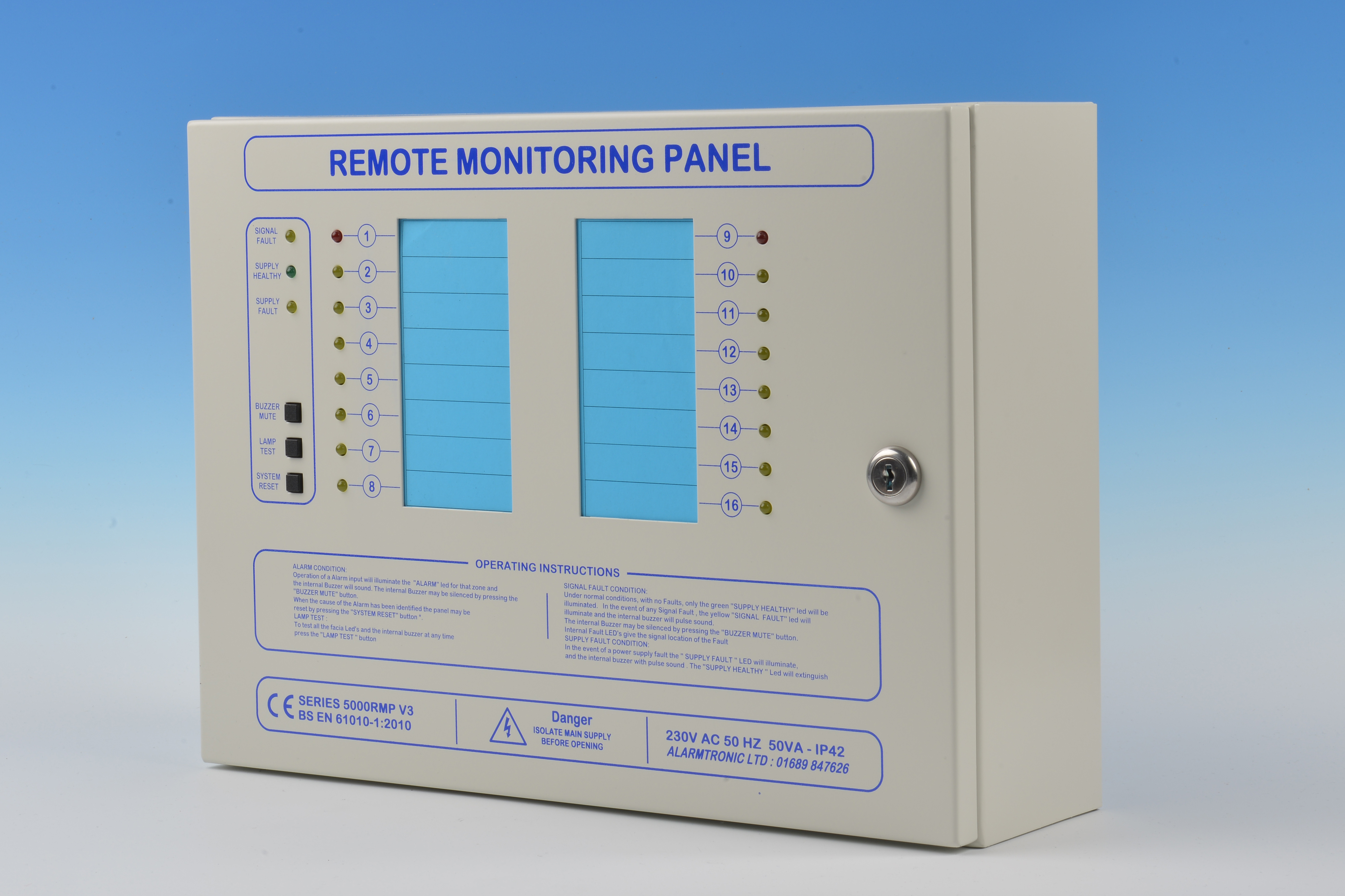
The panel is housed in an attractive metal enclosure with all user controls and indications located on the front fascia together with clear operating instructions . The indicators are identified by removable a channel allocation labels.
A word format template is available for customers to legend the label as required . Blank labels are provided .
A bezel can be fitted to the back Box to enable the control panel to be flush mounted . Special Colours or non standard finishes are available to special order .
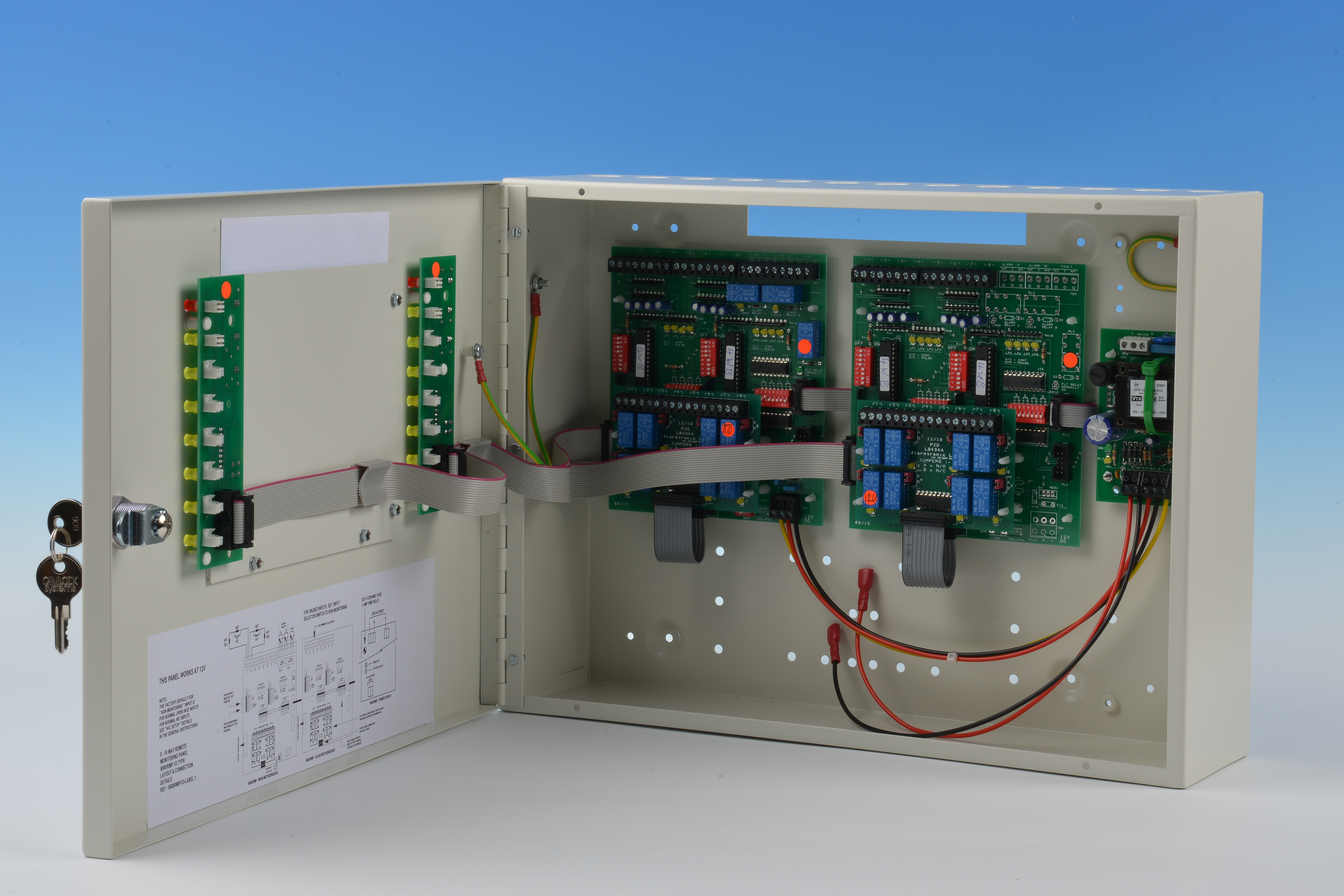
The Series 5000RMP panel provides continuous monitoring of the Status of any Clean contact for both Open & short circuit by using a line monitoring resistor and a Firing resistor. Alternately the panel can via internal individual Selector switches to be set for unmonitored inputs ( IE – no external resistors required ).
The clean contact can be either normally Open or normally Closed as selected by an internal selector switch for each signal. When in an alarm state the appropriate channel LED will illuminate and a internal Sounder will sound. This can be muted by depressing the mute switch. The panel can be returned to its normal mode by depressing the reset switch.
A Common signal “ Line Fault” LED is also provided together with internal individual channel line fault LED’s. The front facia also has Supply Healthy and Fault LED’s. Internal supply LED’s will show either a Charger Healthy or a Battery fault. On any fault condition the Internal sounder will pulse.
A lamp test switch is provided to test all front LED’s together with the internal sounder.
2 Alarm Auxiliary relays (each with 1 set CHO) are provided and each signal can be selected to operate either Relay or no relay as required . A System Fault auxiliary (1 set CHO – fail safe) is also provided .
A optionally channel relay card can be provided to give individual N/O or N/C via internal jumpers.
The channel Alarm LED colour can be changed (Plug-in sockets used for all Channel Indication LED’s) if required.


