Product Description
The PASRP-1A Control Panel is a stand-alone panel intended for use with a Sprinkler Pre-Action Valve assembly and designed to meet the requirements of BS EN 12845 : 2015 and the LPC Technical bulletin 208. The panel has 4 input Fire Zones together with an internal power supply and space for both Standby and Emergency Sealed Lead Acid Battery sets
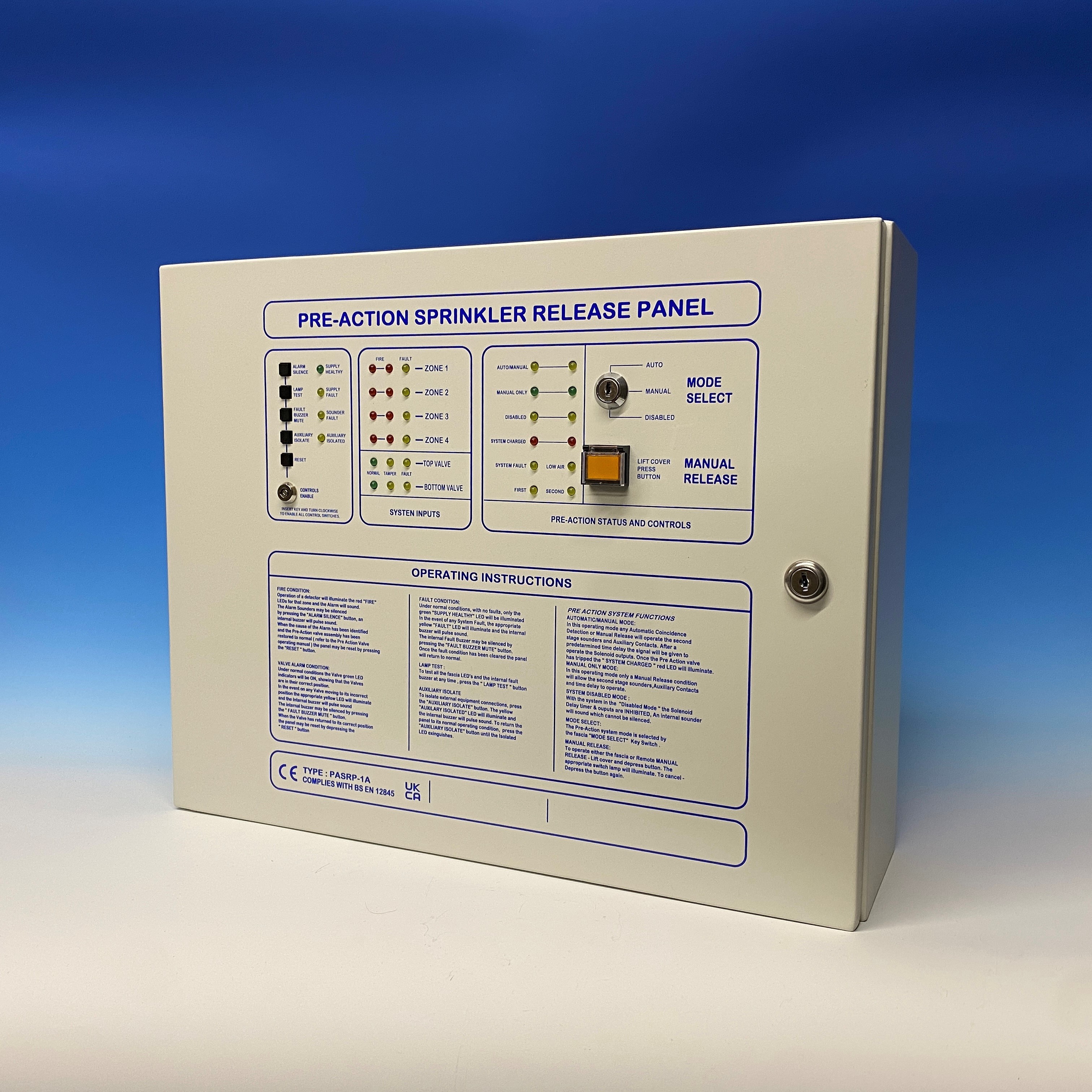
The equipment is housed in an attractively finished metal enclosure with all user controls and indications located on the front panel together with clear operating instructions . A bezel can be fitted to the back box to enable the control panel to be flush mounted .
The “ Alarm Status “ section provides monitoring for four Fire Zones and two Valve Tamper inputs. Status Green LED’s show that the Valves are in their normal operating position. The “ Pre Action Status “ section provides indication and controls for the Pre Action valve assembly. Monitored inputs for Low Air , System Charged, Manual Release & Manual Only Status are provided. Monitored Outputs for two Common Fire Sounders together with two 2nd stage outputs ( Sounder & Beacon ) are provided. The two 2nd stage Solenoid outputs are also monitored for both disconnection and open circuit faults. The monitored Solenoid outputs have an variable ON delay setting (factory set to 40 seconds) before operating together with a variable OFF delay setting (factory set to 40 seconds).
Auxiliary outputs are provided for Common Fire (2 sets CHO) , 1st Stage Operation (2 sets CHO) , 2nd Stage operation (2 sets CHO) , System Charged ( 1 set CHO) and Common fault ( failsafe – 1 set CHO) Remote Pre-Action Status outputs are given for 1st Stage, Manual Only, System Disabled and System Charged .
For the Pre– Action section, front panel switches are provided for Mode select (key operated) and Manual release ( lift flap—push switch ) . The Mode select switch provides for Auto/Manual , Manual Only and Disabled modes. When in “Disabled Mode “ the operation the Solenoid delay timer and outputs are inhibited. An internal buzzer will sound which cannot be silenced.
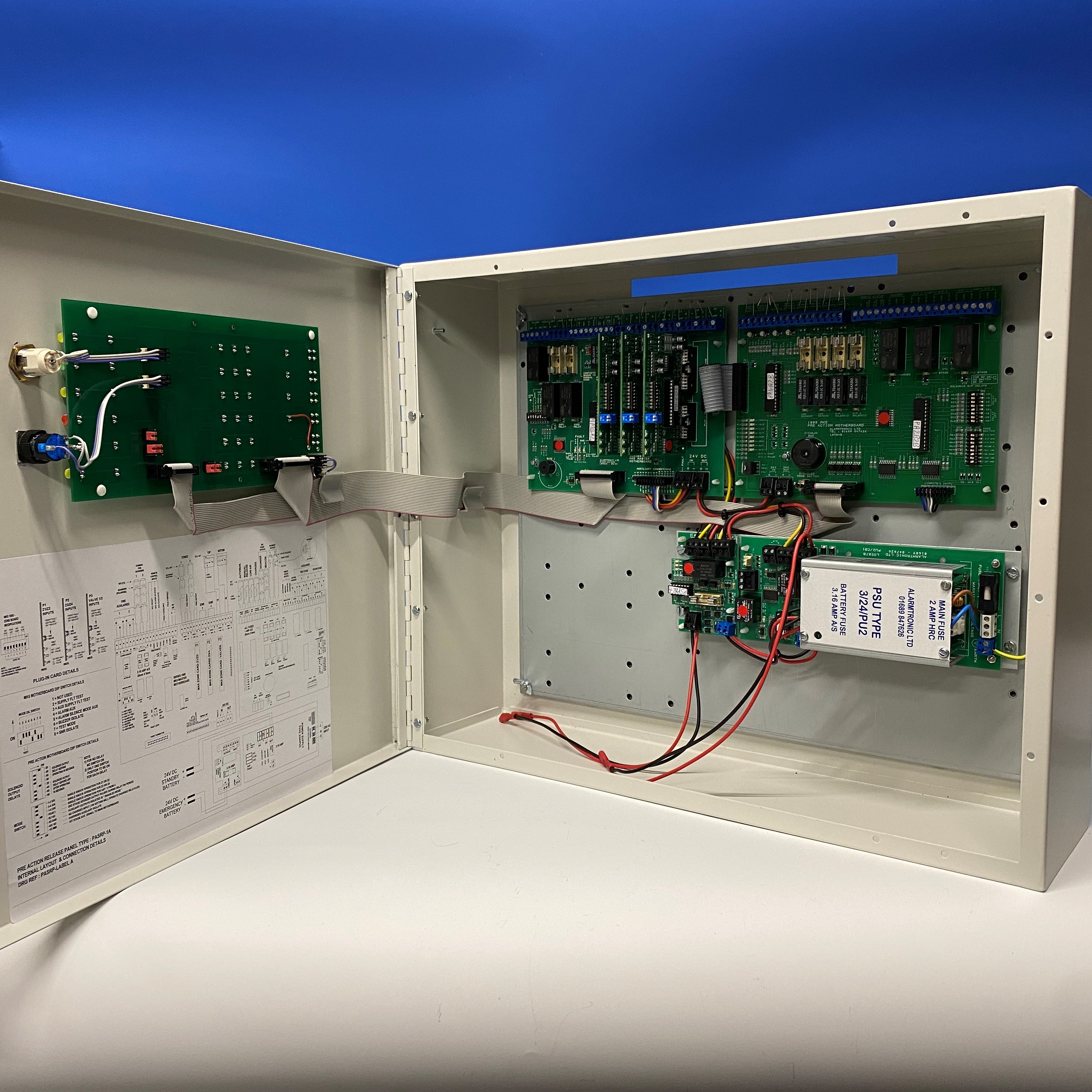
Various Internal DIP Switches allow the user to configure the panel to suit the clients requirements. The operation of the Solenoid outputs can be figured for Single Knock , Double Knock or “Any two from four” Fire Alarm inputs
The Internal power supply provides connection to both the Standby Battery and the Emergency Battery (LPC technical Bulletin 208 supplementary requirement). If both the Primary (mains) and the standby battery both fail , then with the Emergency Battery will automatically operate the Solenoid outputs (failsafe operation). When either of the Primary or Standby battery are re-instated the Solenoid outputs will return to their normal condition.


